screw compressor has excessive vibration
2026-03-10
screw compressor has excessive vibration, but the cause cannot be identified.
Here is a professional and structured version of the text, refined for clarity and flow, suitable for an enterprise website or technical documentation.
Comprehensive Guide to Compressor Vibration Fault Diagnosis & Maintenance
This guide provides a systematic approach to diagnosing and resolving vibration issues in screw compressors, with a focus on maintaining operational efficiency and preventing downtime.
1. Vibration Standards & Measurement
To ensure safe operation, vibration velocity (RMS) must be monitored against the following benchmarks:
- Normal: ≤ 4.5 mm/s
- Attention Required: 4.5 ~ 7.1 mm/s
- Danger (Immediate Action Required): ≥ 7.1 mm/s
Measurement Points: Vibration should be measured in both radial and axial directions at the drive and non-drive ends of the main unit and motor, as well as on both sides of the coupling.
2. Step-by-Step Troubleshooting Procedures
1. Foundation & Installation (Most Common Cause)
- Anchor Bolts: Perform a full-torque re-tightening (refer to the manufacturer's manual) and inspect for foundation cracks or loose shims.
- Levelness: Re-measure using a precision level. If deviation exceeds 0.1 mm/m, re-leveling is required.
- Piping Stress: Check if inlet/outlet hard pipes are exerting force on the machine. Inspect flexible connections for aging or cracking. Install support brackets (spacing ≤ 1.5m) to eliminate resonance.
2. Coupling Alignment (High-Frequency Cause)
- Precision Check: Use a dial indicator or laser alignment tool.
- Radial deviation: ≤ 0.1 mm
- Angular deviation: ≤ 0.5°
- Axial deviation: ≤ 0.2 mm
- Component Check: Inspect the elastic element for damage and bolts for looseness.
- Thermal Compensation: During cold alignment, leave a clearance of 0.1 to 0.15 mm to account for thermal expansion.
3. Lubrication & Oil System (Hidden Killer)
- Oil Quality: Maintain the oil level at the center line of the sight glass. Change oil immediately if it turns black, emulsifies, or contains impurities (use OEM-recommended oil).
- Oil Circuit: Check for clogged oil filters and verify normal oil supply pressure. Insufficient lubrication leads to rapid bearing wear.
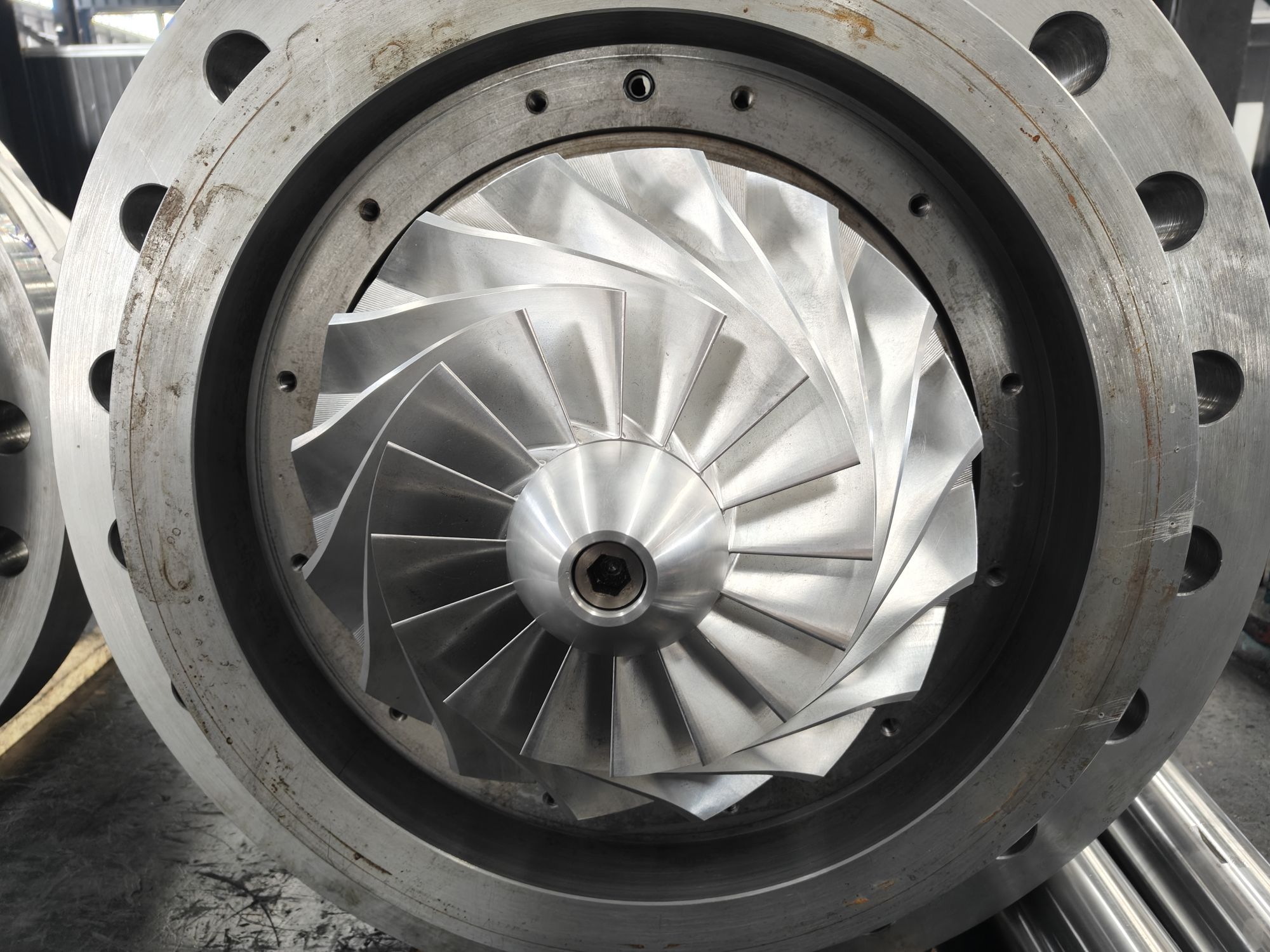
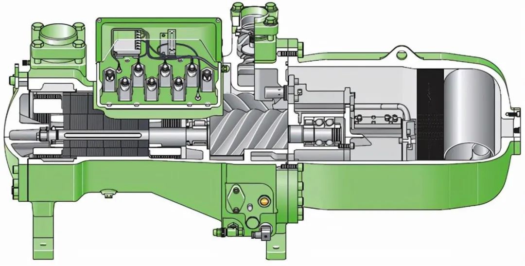
4. Main Unit Internals (Core Components)
- Bearing Check:
- Listen: Use a stethoscope for "rustling/gurgling" sounds.
- Temperature: Monitor bearing housing temperature; a differential greater than 15℃ indicates abnormality.
- Rotor Check:
- High-frequency vibration (> 100 Hz) is often caused by bearing or rotor issues.
- Oil Sludge/Scaling: Requires disassembly, inspection, cleaning, and re-balancing.
- Meshing Clearance: Normal clearance is 0.03–0.05 mm. Excessive wear or clearance requires repair or replacement.
- Axial Movement: Excessive movement due to failed bearing preload can cause the rotor to touch the end cover, resulting in vibration and noise.
5. Motor & Electrical System
- Mechanical: Check for an unbalanced motor rotor, loose fan, or damaged bearings.
- Electrical: Imbalanced current, phase loss, or VFD harmonics can induce electromagnetic vibration.
6. Operating Conditions & Airflow
- Air Path: Check for clogged intake filters, intake pulsation, or exhaust pressure fluctuations.
- Load Dynamics: Frequent loading/unloading cycles or abnormal slide valve operation can cause sudden load changes and vibration.
3. Vibration Spectrum Analysis
When physical inspection yields no results, spectral analysis is essential:
- 1× Frequency: Indicates loose foundations, misalignment, or rotor imbalance.
- 2× / 3× Frequency: Indicates coupling misalignment or early-stage bearing failure.
- Meshing Frequency: Indicates rotor wear or abnormal clearance.
- High Frequency (> 500 Hz): Indicates bearing fatigue or rolling element failure.
4. OEM-Specific Critical Points (Atlas Copco Standards)
Adhering to these specifications is critical for optimal performance:
- Bearing Clearance: Maintain a strict tolerance of 0.03–0.05 mm. Installation outside this tolerance is prohibited.
- Rotor Dynamic Balance: Grade G1 (≤5g·mm). Re-balance is mandatory after cleaning or if dirt accumulates.
- Internal Cleanliness: No foreign objects are allowed inside the main unit. After disassembly, thorough cleaning and torque-controlled reassembly are required.
5. Recommended Inspection Sequence
For efficient troubleshooting, follow this sequence:
- Foundation & Installation
- Coupling Alignment
- Lubrication & Oil System
- Operating Conditions & Airflow
- Motor & Electrical System
- Main Unit Internals

 (Live chat)